Once the box is completed, including painting or stain, the final assembly of the Automatic Timing Light is as follows:
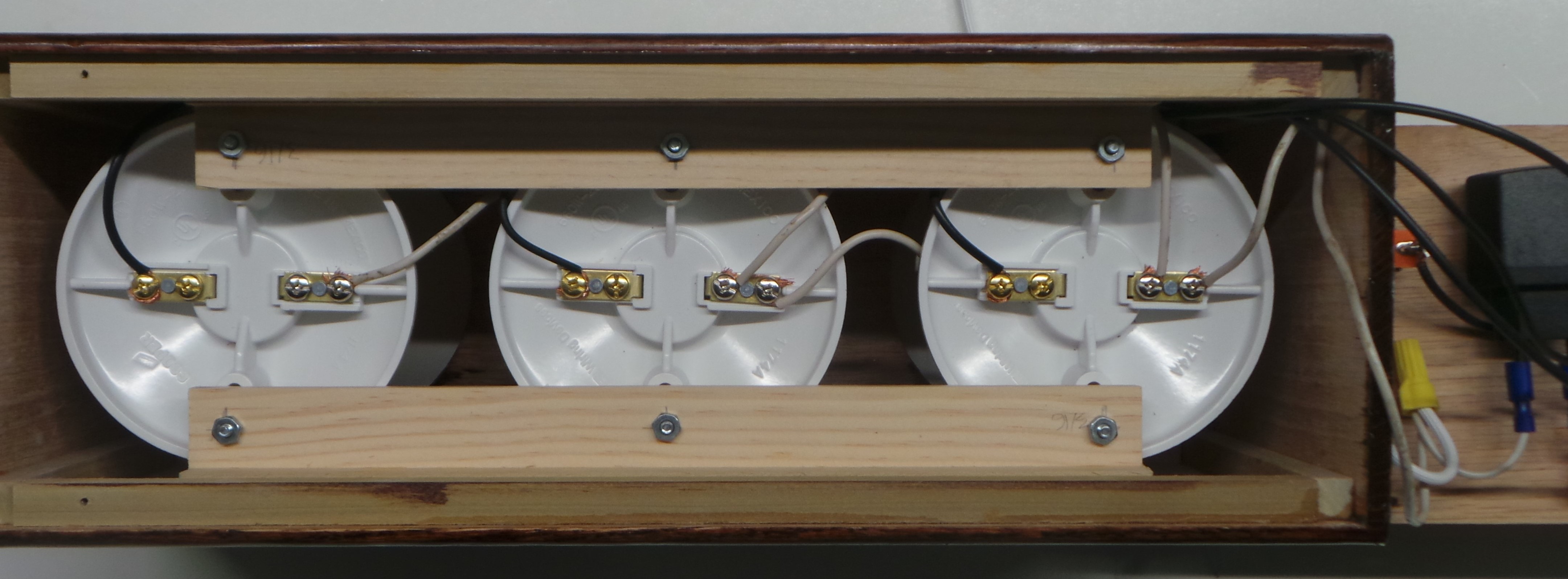
Step 1: Mount the Lamp Holders into the Timing Light Box as shown below. Use the #8 3/4-inch Machine Screws and Nuts to secure the Lamp Holders onto the supports.

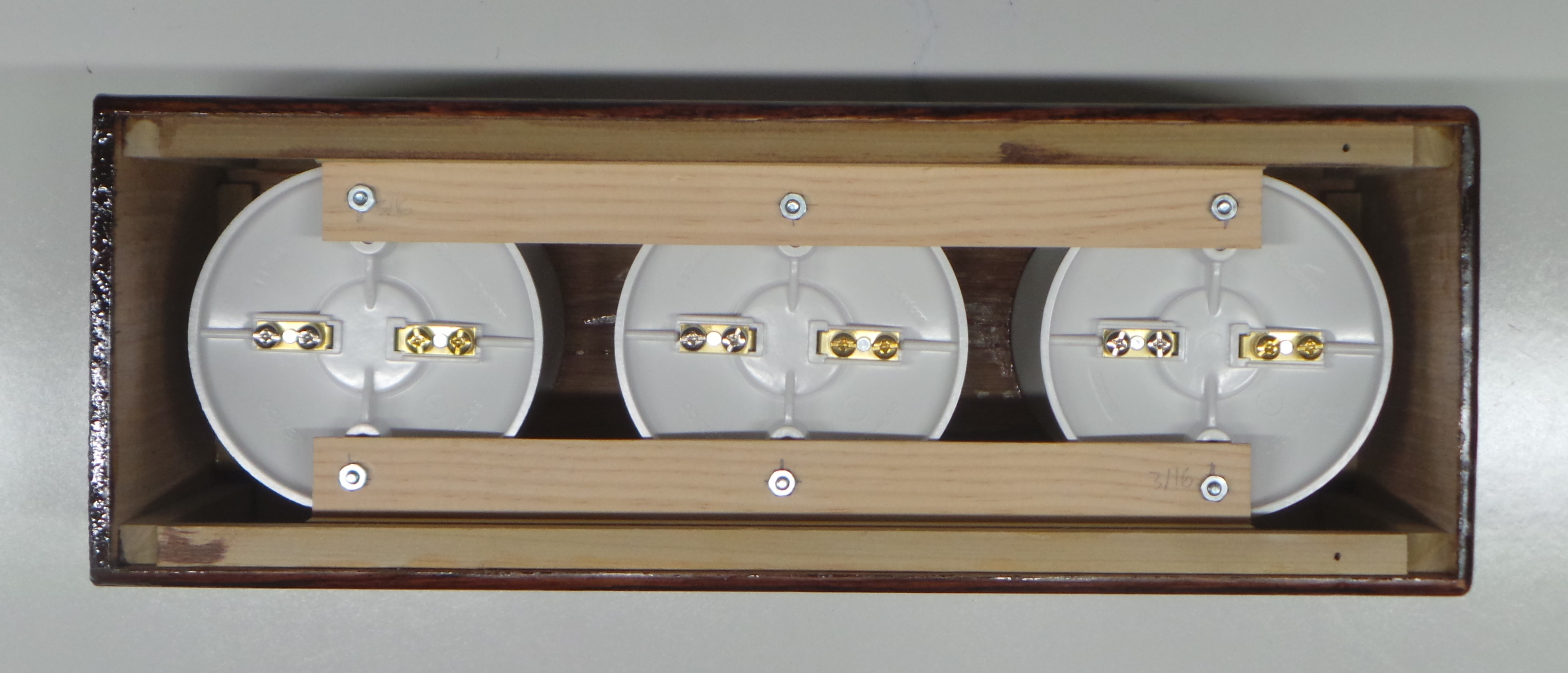
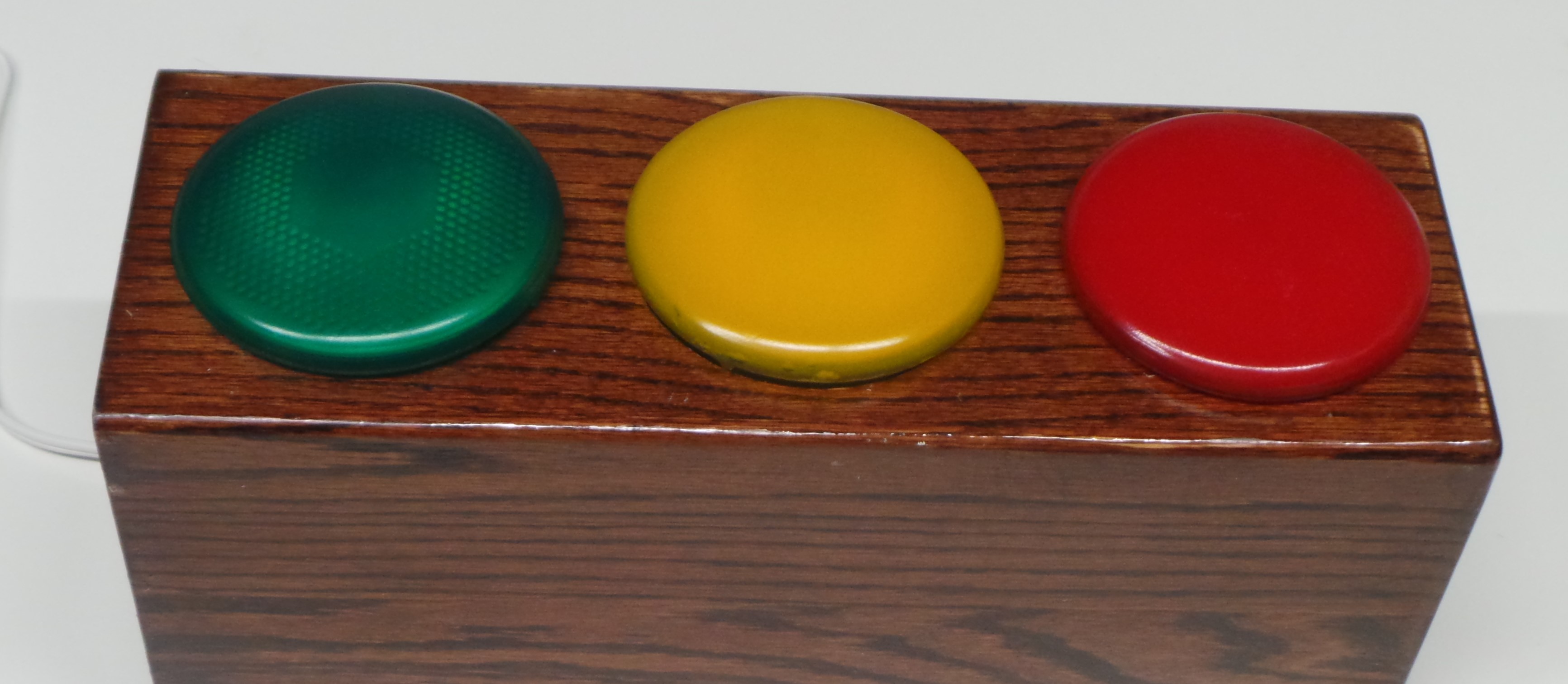
Step 2: Screw the Green, Yellow, and Red light bulbs into their sockets as shown below. This light bulb contacts should engage with the Lamp Holder contacts. You can verify that the light bulbs are touching the contacts by touching a multi-meter to the Silver and Brass contacts at the back. If there is good contact, the resistance will be approximately 12 ohms.
Step 3: Using the remaining two 12-inch lengths of the White 16-AWG Wire connect the Silver terminals of the Lamp Holders together. Run the wire on the front side of the Lamp Holders to keep it out of the way of the electronics.
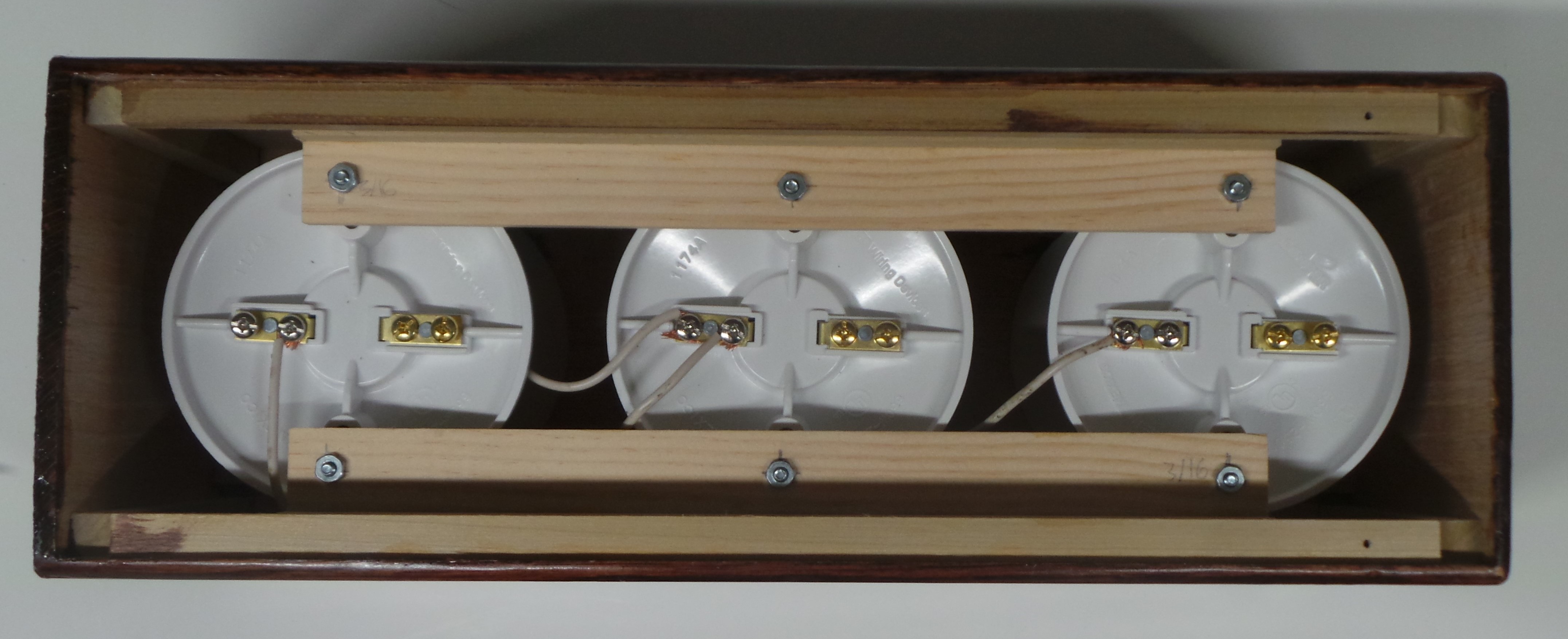
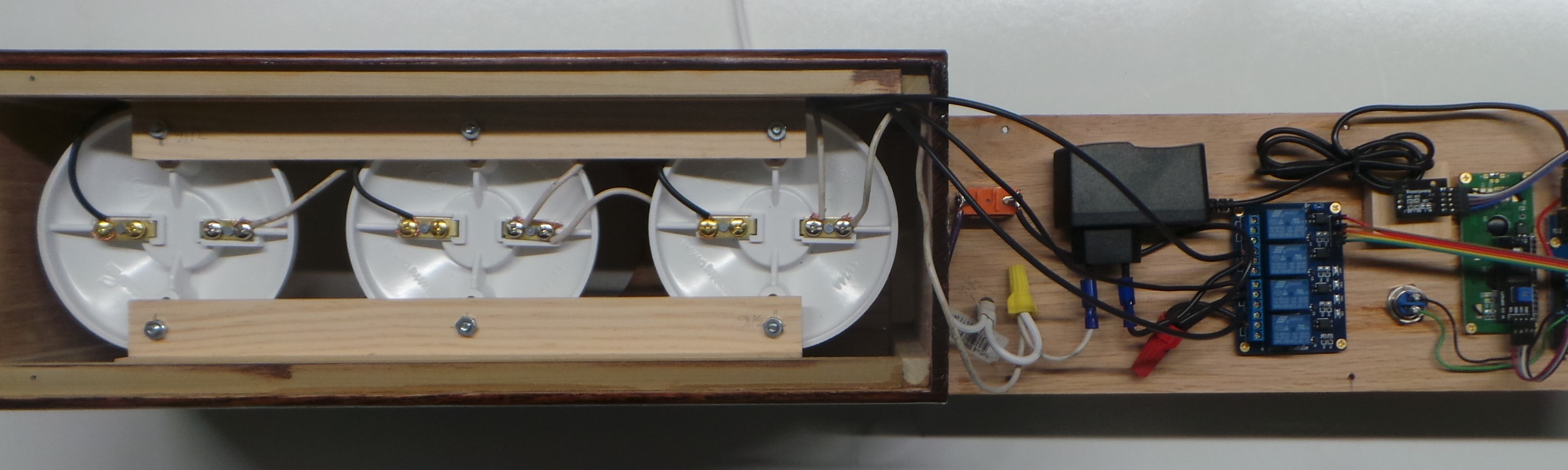
Step 4: Connect the Black wire lengths to the Brass terminals of the Lamp Holders as follows:
- 18″ length (previously connected to Relay Channel K1) goes to the bottom Lamp Holder with the Green light.
- 24″ length (previously connected to Relay Channel K2) goes to the middle Lamp Holder with the Yellow light
- 30″ length (previously connected to Relay Channel K3) goes to the top Lamp Holder with the Red light.
On all of the black wire lengths, run the wires in the front of the Lamp Holders to keep the wire out of the way of the electronics.
Connect the 18″ White wire to the Silver terminal of the bottom (Green Light) Lamp Holder.
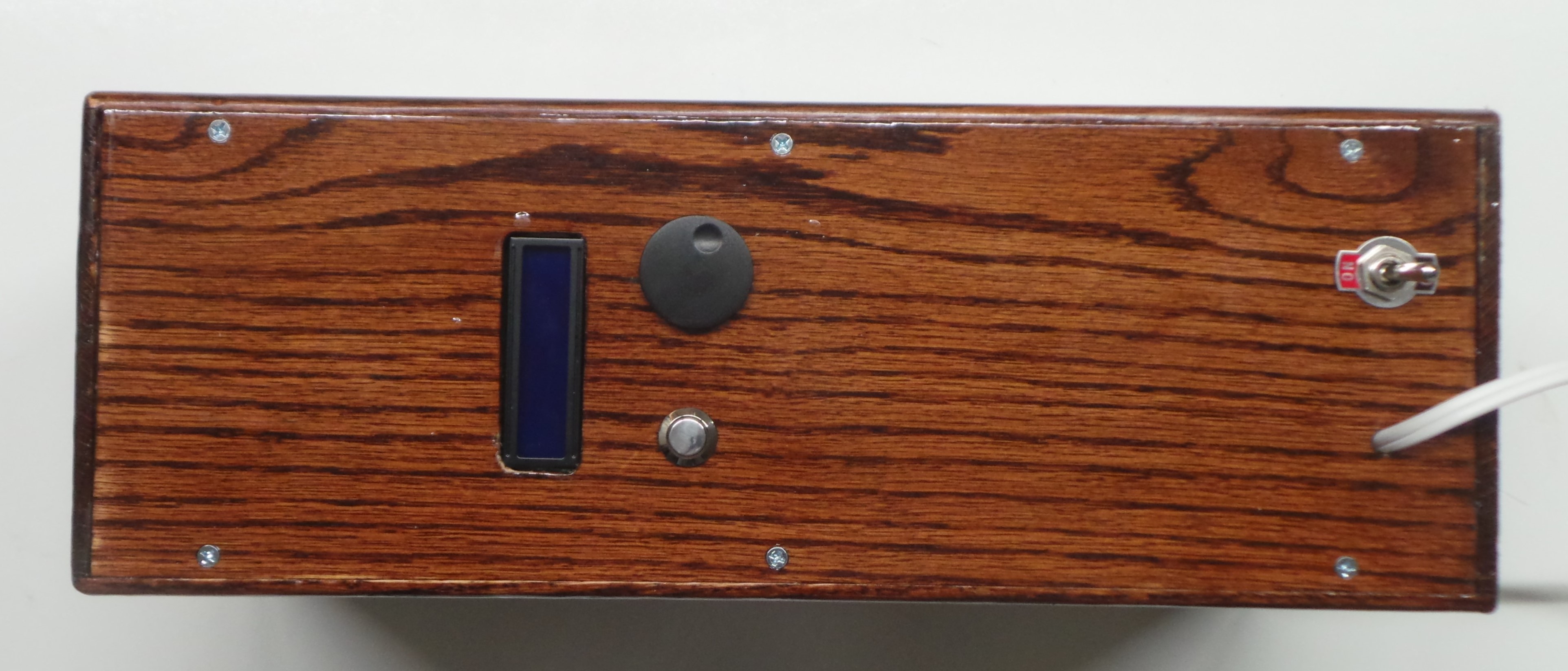
Step 5: Place the back of the Timing Light onto the rest of the box. Make sure that no wires get pinched. Use the 3/32″ bit to drill pilot holes for the screws. Secure the back with six (6) #4 3/4-inch wood screws.
Next: Operation
