Once the Box is fully constructed and Finished (Stained or Painted), the Electronics are assembled as follows. Refer to the Schematic page for schematic diagrams.
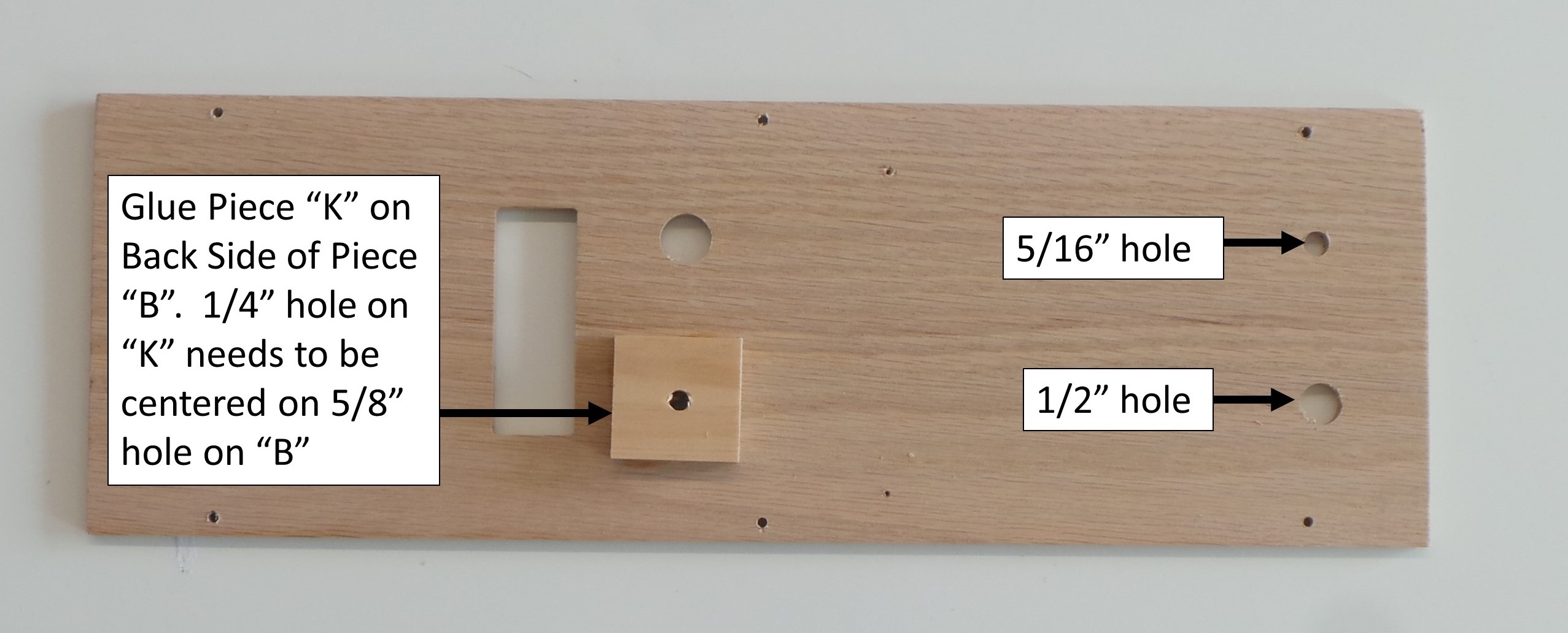
Step 1 – Glue Piece “K” on the inside of piece “B”. Make sure that the 1/4″ hole in “K” is centered on the 5/8″ hole on “B”. “K” is used for the rotary encoder, and should be on the right hole below the LCD when looking at the outside of “B”. Note the orientation of the 1/2″ and 5/16″ holes.
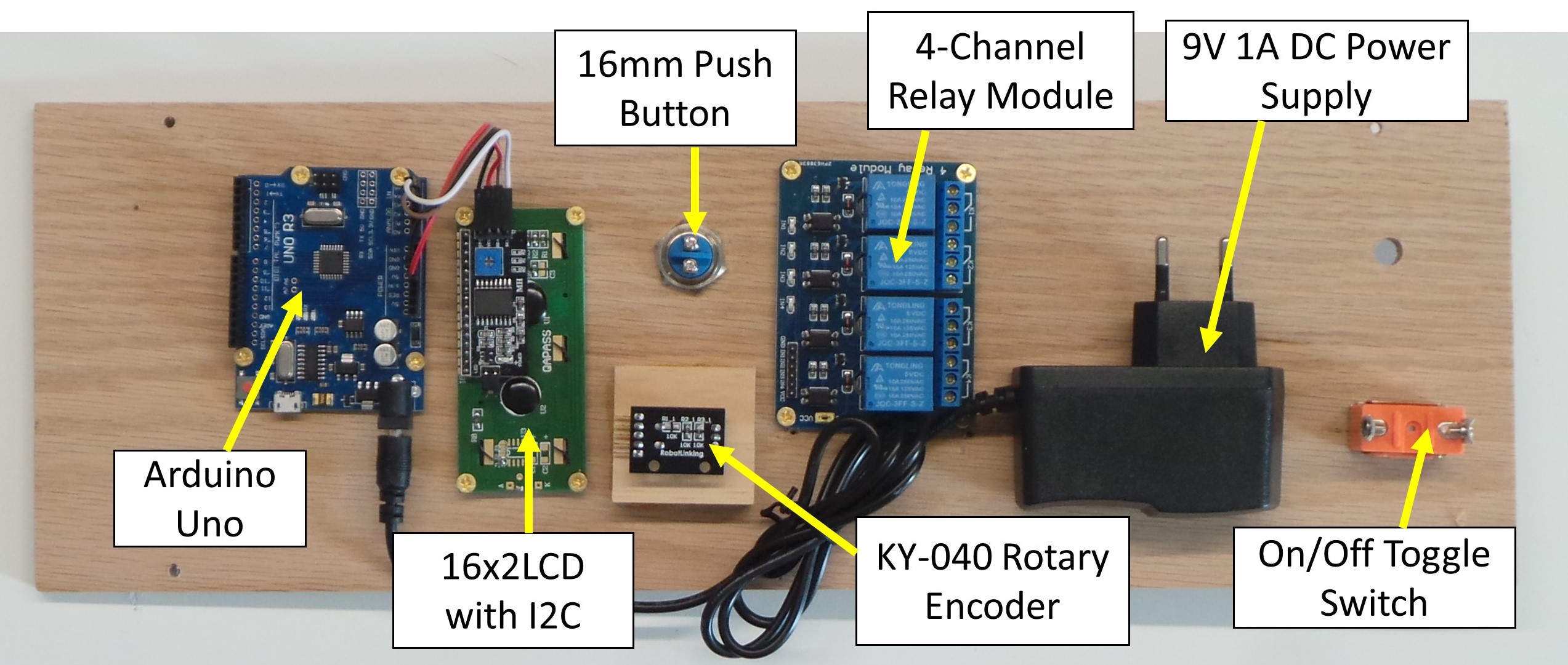
Step 2 – Assemble the electronics hardware as shown below:
- 16×2 LCD inserted into rectangular hole and attached with 3/8″ #4 wood screws
- Arduino Uno to the left of LCD, attached with 3/8″ #4 wood screws
- KY-040 Rotary Encoder screwed into the 1/4″ hole on “K”. Screw it in as far at it goes, and make sure the pins are facing to the left. The Scrubber Knob is pushed onto the stem of the Rotary Encoder from the other side.
- 16mm Pushbutton inserted into the other 5/8″ hole and secured with supplied nut
- 4-channel Relay module to the Right of Rotary Encoder and Pushbutton, and attached with 3/8″ #4 wood screws
- 9V 1A DC Power Supply attached to the Right of Relay Module, via Wood Glue
- On/Off Toggle Switch inserted into 1/2″ hole and secured with included nut
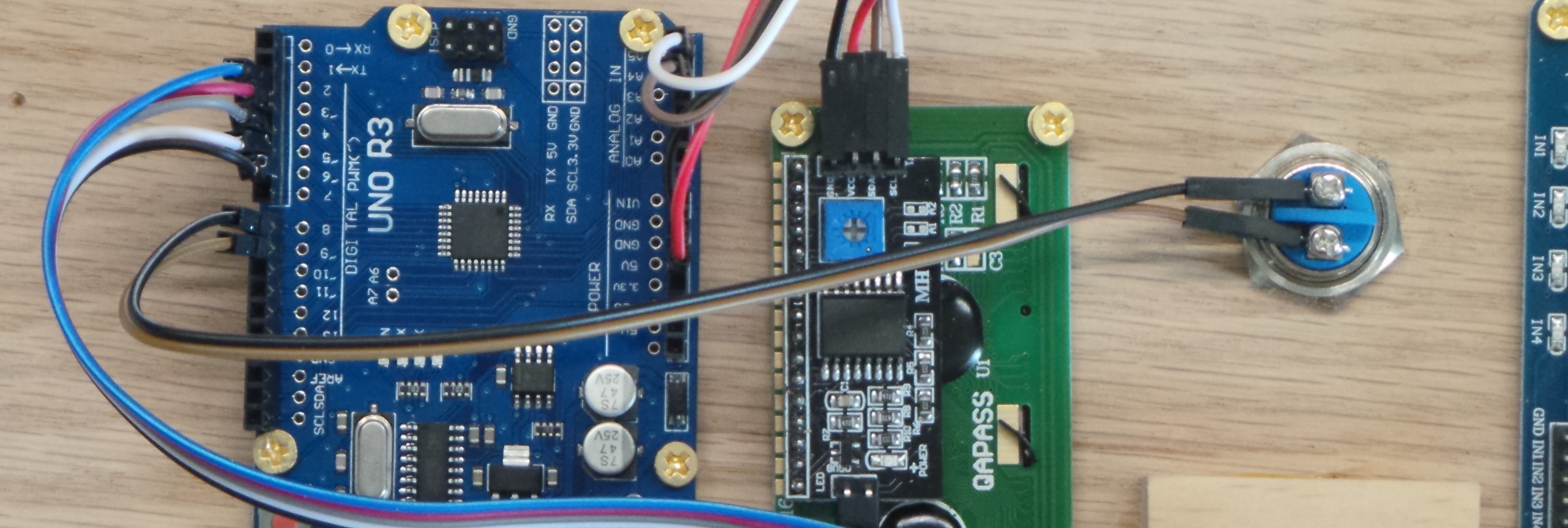
Step 3 – Using the 10cm M-F Jumper Wires, attach the LCD to the Arduino as follows:
- “GND” on the LCD to “GND” on the Arduino
- “VCC” on the LCD to “5V” on the Arduino
- “SDA” on the LCD to “A4” on the Arduino
- “SCL” on the LCD to “A5” on the Arduino

Step 4 – Using 5 of the 20cm M-F Jumper Wires, attach the KY-040 Rotary Encoder to the Arduino as follows:
- “CLK” on the Rotary Encoder to pin 2 on the Arduino
- “DT” on the Rotary Encoder to pin 3 on the Arduino
- “SW” on the Rotary Encoder to pin 4 on the Arduino
- “+” on the Rotary Encoder to pin 5 on the Arduino
- “GND” on the Rotary Encoder to pin 6 on the Arduino
Note: The program software will set pin 5 to HIGH (5V) and pin 6 to LOW (GND) to provider the power for the Rotary Encoder. We can do this because with the Arduino’s internal pull-up resistors, none of the Rotary Encoder pins will draw more than the 20 mA maximum current per IO pin. Wiring this way allows us to have sufficient 5V and GND pins for all components without needing a separate breadboard or splicing wires together.

Step 5 – Using the 20cm M-M jumper wires attach the terminals of the pushbutton to pins 8 and 9 of the Arduino as shown below. Software will set pin 8 to LOW (GND).
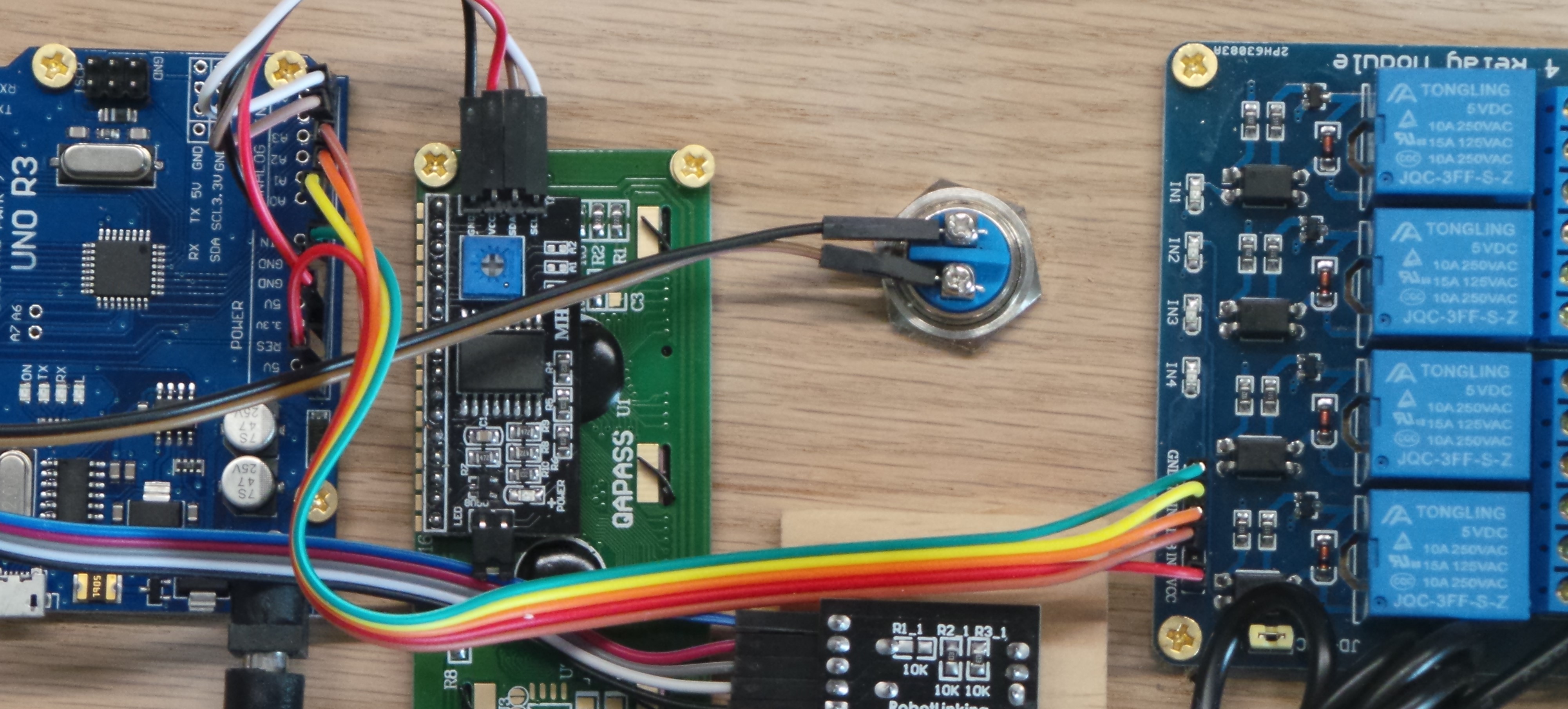
Step 6 – Using the remaining 5 of the 20cm M-F jumper wires, attach the Relay Module to the Arduino as follows:
- IN1 on the Relay Module to Pin “A0” on the Arduino
- IN2 on the Relay Module to Pin “A1” on the Arduino
- IN3 on the Relay Module to Pin “A2” on the Arduino
- GND on the Relay Module to “GND” on the Arduino
- VCC on the Relay Module to “5V” on the Arduino
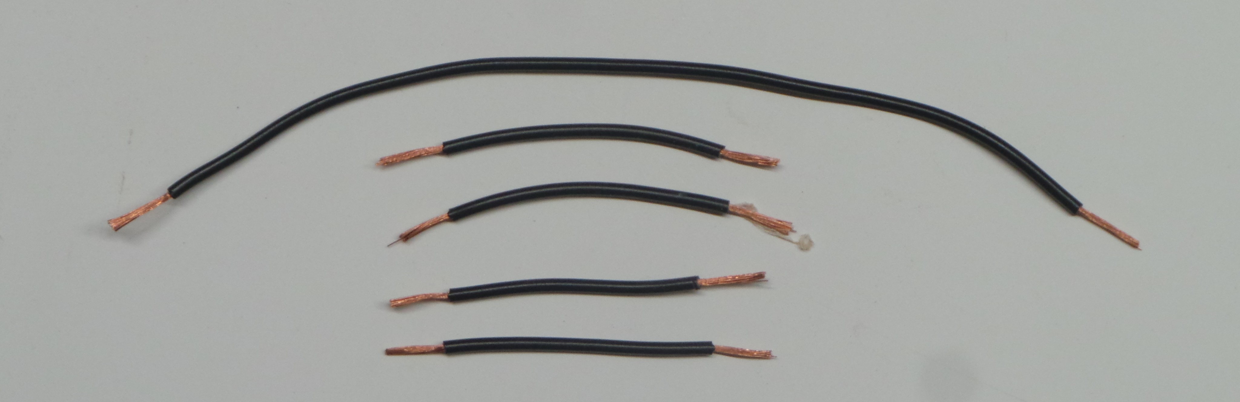
Step 7 – Cut the 16-AWG Black Wire into the following lengths: 4″ (Qty 4), 8″, 18″, 24″, 30″. Strip about 1/2-inch off both ends of every wire. Below is shown the 8″ Length, and the four 4″ Lengths.
Step 8 – Use the Red Wire Nut to tie together one end of the 8″ and four 4″ lengths.

Step 9 – Using a wire crimper, crimp the Female piece of the Bullet Splice pair onto one of the 4″ Lengths, as shown below. Note that the Male piece of the Bullet Splice pair is not used. The Female Bullet Splice will fit on the end of the EU Plug Power Supply.

Step 10 – Connect the three remaining 4″ lengths into the Common (middle) terminal of Relays K1, K2, and K3. Connect the Female Bullet Splice to one side of the 9V Power Supply. Connect the 8″ length to one side of the On/Off switch.

*** IMPORTANT *** The Timing Light is powered by 120V AC Power. Just as you would if working on the electrical power at your home, make sure you check and double-check that the power is off (cord unplugged), before working on or coming in contact with a bare wire. After making the wiring connections, use a multi-meter to check for short or open circuits. For more on working with 120V power, see these articles from Fine Home Building and Popular Mechanics.
Step 11 – Using a wire cutter, cut the Female end off the 6-ft extension cord. Obviously, make sure that the extension cord is not plugged in.
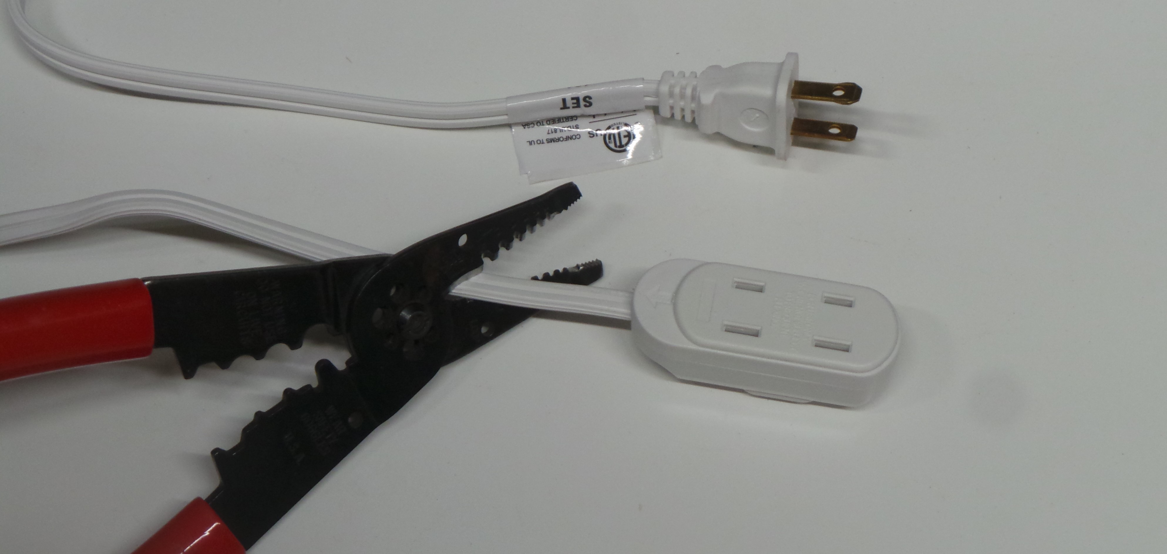
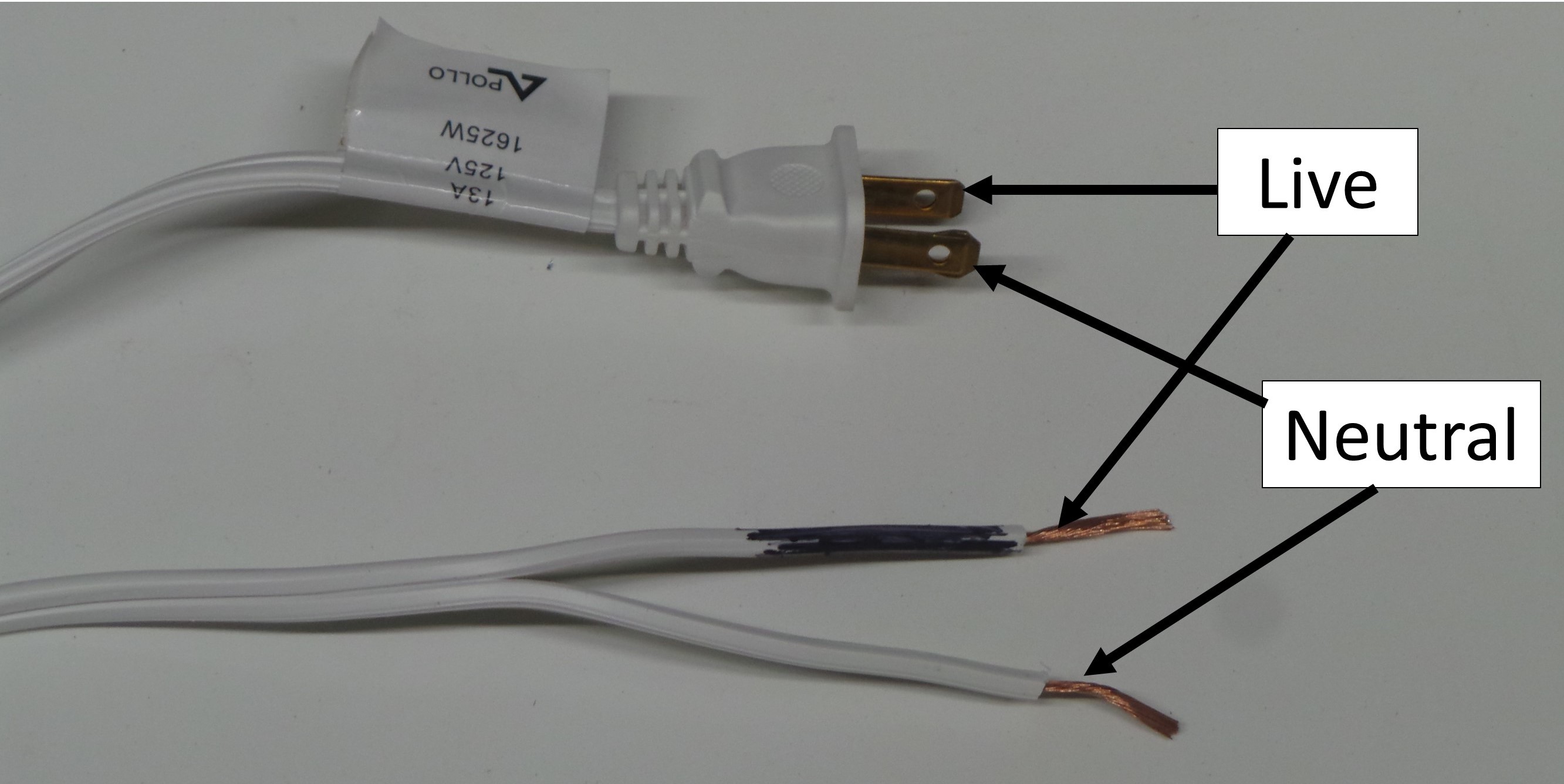
Separate the two wires at the end of the extension cord, and strip about 3/4-inch of insulation from both wires. Note that on US AC outlets, the wide end of the plug is Neutral, and the narrow end is Live. Use a Black Marker to color the bare-wire end of the cord corresponding to the “Live” terminal.
Step 12 – Cut the White 16-AWG wire into lengths of 12″, 12″, 18″, and 4″. Feed the bare-wire-end of the extension cord through the 5/16-inch hole. Use the Yellow Wire Nut to tie together the “Neutral” end of the extension cord, with the 16-AWG wires of lengths 18″ and 4″. Crimp the remaining Female Bullet Splice to the end of the 4″ White wire. Place the Bullet Splice over the remaining terminal of the Power Supply. The 18″ White 16-AWG wire will go to the Silver terminals of the Lamp Holders. Attach the “Live” (marked with Black) end of the extension cord to the remaining terminal of the On/Off switch. Wrap electrical tape around the extension cord near the hole, to prevent the cord from pulling out of the hole.
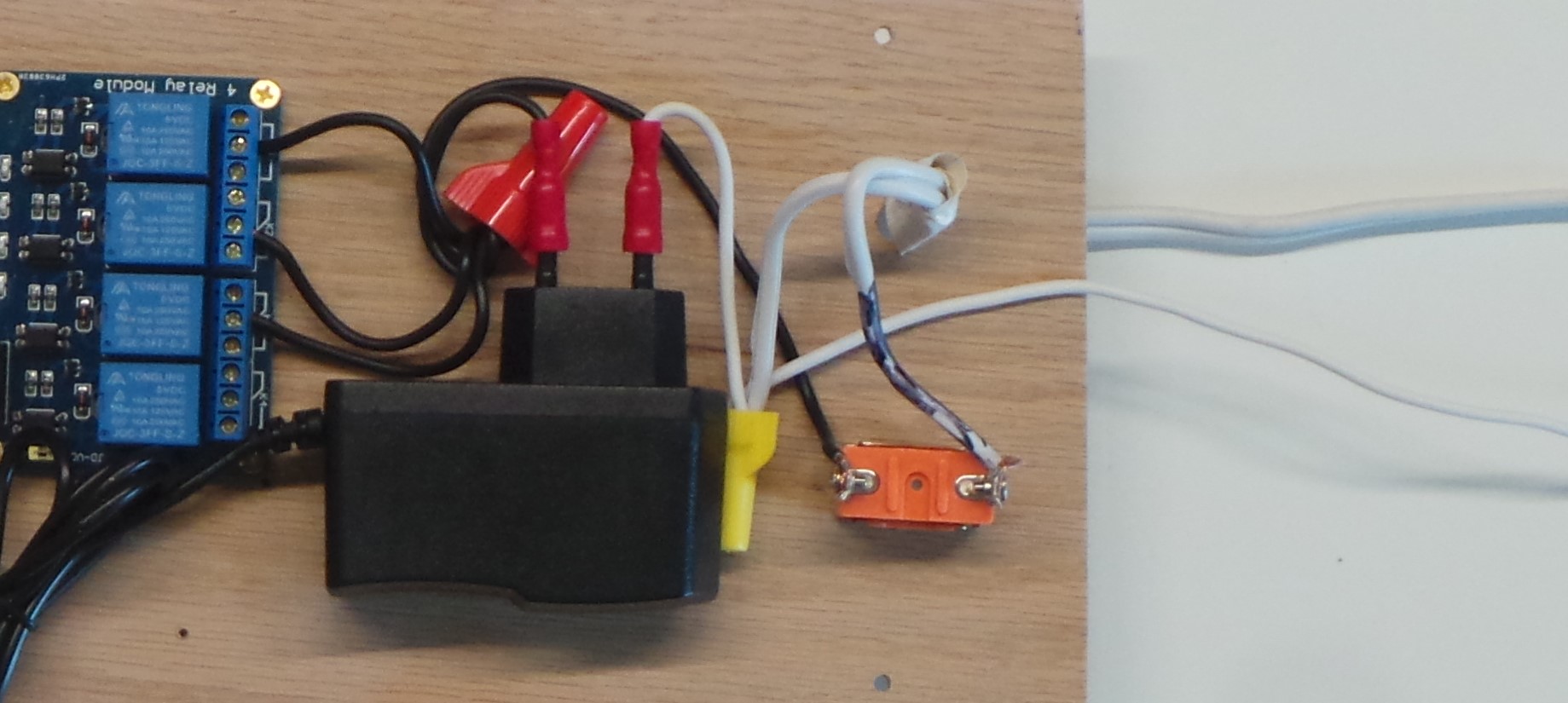
The project wiring will look like below:
Step 13 – Connect the remaining black wires to the Normally Open (NO) contacts of the Relay Module as follows:
- 18″ Black Wire to NO on K1 – This will power the Green Light
- 24″ Black Wire to NO on K2 – This will power the Yellow Light
- 30″ Black Wire to NO on K3 – This will power the Red Light

Next: Software
